

| Channel Strip ToolKit Noise-Gate The Noise-Gate of the ToolKit offers extremely fast attack and independent control of all parameters. Standard applications like cleaning up a drum kit are no problem at all. Even with extrem settings, the noise-gate operates free from click noise and without cutting transients. The hysteresis-free design allows precise adjustment of the threshold and the wide range high-pass and low-pass filters make it easy to limit operation to a certain frequency band. In addition to the standard applications, extensive envelope processing is possible with all kinds of audio signals. The ToolKit Noise-Gate is also available as TM116 ToolMod Pro Audio Module |
 |
| Home | Processing | Mic-Pre | Compressor | Noise-Gate | Equalizer | Limiter |
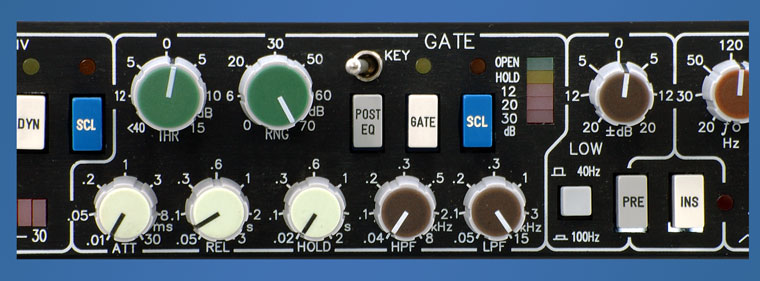
Threshold and RangeThe Threshold control has a range from + 15 dB to below -40 dB, which is more than sufficient for any application of a noise-gate. The Range pot controls the attenuation of the gate in the off state. The maximum attenuation is more than 70 dB. This pot has an expandedrange from 0 to 10 dB that allows a precise adjustment of very small attenuation values that are necessary when using the device to fade down background noise without audible breaks. The ToolKit noise-gate produces no click noise or any other disturbance as side effect of the regulation. Even if a 10 Hz square wave is applied to the key input chops the audio signal with all time controls set their minimum values, the switching noise is far below - 70 dBA. The fade in is optimized to reduce the side effects that are connected to fast levels changes and switching of audio signals by the additional components that are added to the spectrum. The fade out law is dB linear, which offers the best possible performance. AttackThe Attack time meets the requirements described in detail in the info box, when it is set all to the left. It can be adjusted to fade in times up to 30 ms. With any setting, the fade in character is not linear but optimized in a way that the main part of the attack time fades the last 10 dB while the fade from the level set by the rangepot to - 10 dB is always very fast. This principle offers a much better result. Hold and Release>The Hold control determines the time the gates remains open after the level has dropped below threshold. The Release control sets the fade down speed from the 'on' level, which is always 0 dB, to the level that is determined by the range control. The release time starts at the end of the hold time. The release control lets you set the fade speed from 50 ms, which actually is more a switch off than a fade, to 3 seconds, which is a slow fade out. However, 50 ms are fast enough for a hard cut-off without additional click noise caused by spectral consequences of a faster fade out time. The hold time ranges from 20 ms (noHold) to 2 seconds. The minimum hold time is adjusted to prevent the Gate from bouncing but to produce no audible hold effect. This feature makes it possible to implement the threshold circuitry without hysteresis, that always results in a blurred adjustment of the envelope settings. The ranges of hold and release cover all possible applications of a gate. FiltersIt is often necessary to limit the reaction of the gate to a certain frequency band. For the use of the noise-gate with a drum kit the function is indispensable, since the filters make it possible to determine that the gate will only open if the level exceeds the threshold in the frequency band of the particular instrument that is assigned to this gate. The sweep ranges of these filters must be very large compared to filters that are used with audio signals, to be able to use this principle with all instruments in a sensible way. The ToolKit noise-gate has a sweeped high-pass and low-pass filter with a steepness of 12 dB/oct. The sweep range of these filters covers the part of the audio band that is of interest for this function and ranges from 40 Hz to 8 kHz for the high-pass and from 15 kHz to 50 Hz for the low-pass. The filter is always active, therefore you should take care that it is set to the positions on the pictures if you want to use the gate in wide range mode. Side Chain ListenThe SCL (side chain listen) switch is important, since it allows switching the input of the gate's side chain, which is the output of the filter section, to the output of the gate. With this mode adjusting the filters becomes very easy, since you hear the filter output instead of the output signal. Remote Control and external FiltersThe Key input allows remote control of the gate by another signal that can be connected to the key input jack. Actually, the key input is an insert point with input and output. Key insert input and output are fully buffered and balanced, and able to handle levels of more than + 30 dBu. The input signal of the gate section feeds the key output. External filters to process the gates side chain signal can also be used. A lever switch selects the key input. The internal filter section is located post the key input. It is therefore possible to use the filters and the side chain listen function also together with external control signals. The output of the key insert section has higher output impedance that makes it possible to parallel several outputs, just by an external cable. Stereo LinkAlthough stereo coupling of noise gates is not very important, you can use the same principle for the gate as for the compressor and bridge the key outputs of the devices that you want to link. The only side effect is that you will need to readjust the threshold. The key switch selects linked operation. Of course, matched settings of the linked noise-gates are necessary for proper operation. DisplayA LED chain displays the operation mode of the gate. A green LED shows the OPEN state, a yellow LED the HOLD state. The actual attenuation when the gate is closed is displayed by 3 additional LED?s at 12, 20 and 30 dB. The entire section is bypassed unless the GATE switch is pressed. RoutingThe gate is inserted post compressor and pre equalizer in the default position. The POST EQ switch moves the gate post the equalizer. In case that the compressor is also switched post equalizer, the gate is still post the compressor. It is possible to alter these basic settings virtually by connecting the key input of the gate with the side chain insert output of the compressor. When the noise-gate is switched to key mode, it is now controlled from the input of the compressor, which has the same effect as moving the entire gate pre compressor. |
|

PRO AUDIO :
|
AUDIO MODULES :
|
| SURROUND SOUND |
| MIXING CONSOLES |
| Where to buy | |||
| Download | |||
| Reference List | |||
| Audio Studios | |||
| Links | |||
| Link to us | |||
Imprint
|
| At a glance a noise gate is a simple device that does nothing else but switching the output on and off depending on the level of the input signal. This point of view is okay for a two way radio or things like that but not for a noise-gate that can be used with professional audio applications without a very unhappy looking audio engineer. A noise gate has to deal with a couple of different problems. The most important problem is the attack time. If the gate opens too slow, it is simply useless. Such a behavior will modifiy any sound that is treated, and that is unacceptable. Problem no. 2 is click noise. If the gate produces any click noise, its also useless. All other problems are a lot easier to handle.
Any technical system has a response time. This is not a problem of a particular device but a physical principle. As far as a noise-gate is concerned, the time from the point where the input signal exceeds the threshold level to the point when the gate is open is the crucial property of the gate. With acoustic signals, one of the most important applications of a noise-gate is to improve crosstalk between the different microphones of a drum kit. Without a gate, the crosstalk between the different instruments of the drum kit is in a range that makes it almost impossible to treat the different signals in a way that the drum kit sounds like it is supposed to sound. Kick drum and snare alone require a lot of additional signal processing. The sound of any percussive instrument is recognized during the attack phase. Slightest modifications of the attack phase result in huge audible differences that cannot be repaired later. The first 20 microseconds determine the sound of a kick drum, a snare, and a hi-hat and all other percussive instruments. |