
| OPEN IN NEW WINDOW/TAB | HOME | TOOLMOD PRO AUDIO | CLOSE | TM132 HOME | CONTACT |
Control Elements
M/S Stereo Mastering Compressor
- ToolMod Pro Audio - TM132
M/S Stereo
Mastering Compressor Home | Stereo
Mastering Home
| Control Elements | Details and Specials | |
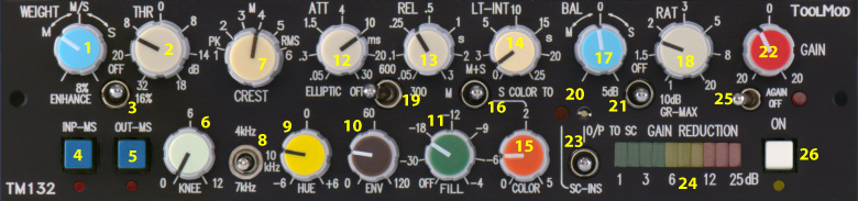
| 1 | Weight Control, determines the control signals that
feed the control section of the compressor. Center position - M and S channel are weighted identically the channel with the higher level controls the compressor M position / all to the left - only the M channel controls the compressor S position / all to the right - only the S channel controls the compressor With stereo operation, Weight controls the left/right balance (L = M; R = S) |
Crest The Crest setting affects the behaviour of the ac/dc converter. Weight Balance Envelope HUE Since the compressor regulation is proportional to the spectral density of the input level, the effect of the Hue filter depends on the levels in the mid/high range (high mid/high level = more effect and vice versa). Autogain Side Chain Insert The format of the side chain insert is identical to the operation format of
the compressor: Like audio inputs and outputs, the side chain insert is electronically balanced and can handle levels of + 30 dBu. Operation Mode: Input L/R - INP-MS not pressed -> M/S Mode The OUT-MS swtich (pos 5.) determines only the format of the output, not the operation mode. Stereo Mode: Matrix Options:
|
| 2 | Threshold Control regulation takes place with input levels above threshold control range +18 dB to -32 dB |
|
| 3 | Stereo Base Enhancement; OFF (@ center position), 8 % or 16 % over base |
|
| 4 | INP-MS, selects the input format normal - input in stereo format L/R pressed - input in m/s format |
|
| 5 | OUT-MS, selects the output format normal - output in stereo format L/R pressed - output in m/s format |
|
| 6 | Soft-Knee control with range from 0 dB to 12 dB. In the 0 dB position, the transition from the unregulated level range below threshold to the regulated range above threshold is hard. Any other position causes a soft knee characteristics, which means that the transition takes place over a level range that matches the setting of the control. | |
| 7 | Crest Selector, 6 position stepper switch RMS - long integration time, RMS characteristics Peak - short integration time, peak characteristics M - medium integration time, compromize between peak and RMS - see Details and Specials for more |
|
| 8 | HUE Filter frequeny selector, 3 positions, 4, 7, and 10 kHz (see 9.) | |
| 9 | HUE: Side Chain Shelving Filter that affects the high mid and high range with +/- 6 dB range and selectable frequenceis (see 8.) Modifies the behavior of the compressor regulation for the selected frequency range (more or less mid/high frequency compression) |
|
| 10 | Envelope Control improves the compression of low frequency signals range 0 = Off to 120 Hz - see Details and Specials for more |
|
| 11 | Fill mixes the uncompressed input signal to the compressed output signal. This function can cover unwanted side effects of hard compressor setting. The range is from off to - 4 dB. | |
| 12 | Attack control with range from .05 ms to 30 ms for 10 dB attenuation. Determines the response time of the regulation to an increase in level | |
| 13 | Release control with range from 50 ms to 3 sec. Determines how fast the compressors reduces the attenuation when the input signal drops down. | |
| 14 | LT-Int adds a second release component, that is calculated by a long time integration of the signals envelope. The control can add some variety to the compression. In addition it makes possible to reduce the release time setting without causing low frequency distortion if an appropriate setting is selected. | |
| 15 | Color adds 2nd harmonics to the output. With the pot all to the right, ~ 2 % static harmonics (static = with no compression) are added and ~ 6 % of dynamic harmonics (dynamic = amount of harmonics depends on the gain reduction) at 10 dB gain reduction are added. The relation between static and dynamic harmonics can be internally adjusted and adapted to your needs. The absolute percentage depends on the output level. The values above refer to + 6 dBu/+ 4 dBV. | |
| 16 | Color Routing: M/S (center position) - Harmonics are mixed to M and S M (to the left) - Harmonics are only mixed to M; only the center of the stereo signal is affected S (to the right) - Harmonics are only mixed to S; the center remains free from harmonics, harmonics appear in the room only |
|
| 17 | Balance determines the linking of the compression in
the m and s channels @ center - M and S are precisely linked, to the left - M -> compression is reduced in the S channel to the right - S -> compression is reduced in the M channel (see right column for more details) |
|
| 18 | Ratio Control, adjust the compression ratio for signals
above threshold. control range 1:1 = no compression 2:1 = a signal of 10 dB above threshold is reduced to 5 dB 20 : 1 , quasi limiter operation, 10 dB above threshold is reduced to 0.5 dB |
|
| 19 | elliptic Equalizer, 3-position switch, OFF, 300 Hz, 600
Hz increases the crosstalk in the low frequency range to 15 dB @ 300 Hz or 600 Hz to center the bass foundation |
|
| 20 | LED indicator for Side Chain Insert / O/P to S-C switch (see 23.) | |
| 21 | 3-position switch; Limits the maximum gain reduction of the compressor to 5 or 10 dB | |
| 22 | Gain control with calibrated center position and center detent, range > +/- 20 dB. The gain control affects the output level post compressor | |
| 23 | 3-position switch; Activates the side chain insert or
switches the side-chain input to the output This function makes checking the setting of external eq's an filters a lot easier - see Details and Specials for more |
|
| 24 | LED chain with 10 LED's, displays the actual gain reduction display range from 1 dB to 25 dB |
|
| 25 | Disables the Autogain function - see Details and Specials for more |
|
| 26 | Bypass switch | |
| Sitemap |