

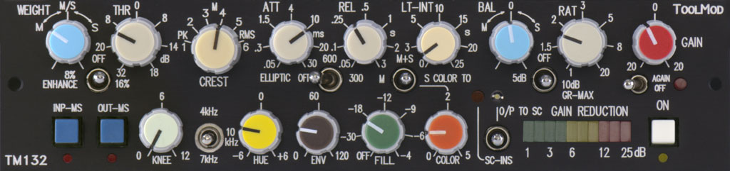
 ToolMod Pro Audio ToolMod Pro AudioM/S Mastering Compressor TM132 M/S Stereo Mastering Compressor with special Features for real M/S Dynamic Processing with high Loudness Gain The M/S Stereo Mastering Compressor TM132 offers the same high loudness gain without the typical squeezed sound of a compressor as the TM222 Stereo Mastering Compressor. In addition to all features of the TM222, the TM132 M/S Compressor comes with a set of features for dynamic processing in the M/S stereo format. The module can be used as a conventional stereo compressor as well. Using the assortment of additional, uncommon features can result in 10 dB loudness gain or even more. In spite of this massive loudness gain the compressor maintains the original transients, the audio signal still sounds natural but with a subjective impression of density and dynamic. A mix sounds 'loud' but not compressed. |
Highlights:
all M/S Modules:
Alternatives:
|
|
Loudness gain is the most important issue of stereo mastering compression
in L/R format and M/S format as well. Conventional compression principals often
cause poor results as far as the loudness is concerned. Audible side effects
like pumping and/or distortion in the low frequency range, limit the possible
compressions rates. Very often, the mix looses its originality, sounds squeezed,
and is only loud but not natural anymore.
The M/S Stereo Mastering Compressor TM132 has been optimized for massive loudness gain. A set of additional functions can compensate the negative side effects of high compression rates that are caused by physical and physiological limitations in some extend. Using these functions appropriately and adapted to the audio signal can result in massive loudness gain of 10 dB or even more. A mix processed in this way sounds still natural and simulates a subjective impression of dynamic. This principle of master compression has been used in the extensive master sections of our large format consoles for more than 20 years and has been improved in many little steps. The control ranges of all parameters are more than sufficient to cover common settings very well. This results in a very high variability of the characteristics that can simulate almost all standard compressor settings M/S Compression Specials - Weight, Balance, and I/O Matrix
The Weight and the Balance pots determine the behavior of the
mastering compression in M/S mode. Please read the M/S Compression Basics for information on the principle.
The WEIGHT pot determines which channel
controls the compression. As long as this pot is at the calibrated center position,
the M and S channels control the compressor equally, meaning that the channel
with the higher momentary level controls the compressor. In M/S mode, this is
almost always the M channel. Right hand rotation of the Weight pot forces the
S channel to control the compressor while left hand rotation forces the M channel.
All to the right, only the S channel controls the compressor while all to the
left, only the M channel is active. It is possible to change the standard behavior
of the M/S compression from 'M only' to force the S channel or reduce or even
disable the S channel. Since the Weight pot affects the input of the control
section, the linking of the audio channels is not altered by the setting.
While the Weight pot affects the control chain of the compression, the BAL(ance)
pot changes the audio path by modifying the linking. At the center position,
M and S are precisely linked. All other positions more or less decouple both
channels and reduce the compression in the M channel, when turned to the right,
or in the S channel, when turned to left. This results is dynamic modulation
of the stereo base width. In rare cases, depending on the particular mix, this
might result in some nice spatial effects; however, in most cases such a setting
is useless, since the positions of the instruments on the stereo base are not
stable anymore. Please check the M/S
Compression Basics for details
To use the TM132 M/S Mastering Compressor in M/S mode, a format conversion from the common L/R stereo format to the M/S format at the input and reconversion of the output signal from M/S to L/R is necessary. Since these matrix stages are integrated in the module, the compressor can be used in M/S mode with standard stereo signals in L/R format without the need of additional, external matrix stages. The switches IN-MS and OUT-MS control the internal input and output matrix stages independently. Since the input and output format can be switched in and out it is possible to integrate the M/S compressor into a M/S processing chain with several M/S modules.
The IN-MS and OUT-MS switches determine the input and output format and the operation mode of the compressor. As long as these switches are not pressed, the matrix stages are active; pressing a switch bypasses the particular matrix. If both switches are not pressed, the compressor operates in M/S mode with input and output signals in L/R format and in stereo mode with input signals in M/S mode. If both switches are pressed, the compressor works in stereo mode with L/R input and output signals and in M/S mode with M/S input and output signals. Pressing a single switch just alters the format of the input or output.
With the standard factory setting, the bypass switch is a relay hard bypass that affects the compressor and the input and output matrix stages. This setting is practical if the compressor is used either with L/R or M/S input and output signals. If the module is integrated in a M/S processing chain, e.g. in combination with the M/S Stereo Equalizer TM133, and either the input or the output the compressor is used to convert or reconvert the format from or to L/R, the standard setting of the bypass switch results in an unwanted format conversion. The alternate setting keeps the matrix stages always in the signal path and the bypass switch only affects the compressor. However, the matrix switches IN-MS and OUT-MS are always functional and can be used to switch over from L/R to M/S operation of the compressor. The setting can be changed by jumpers at any time.
Compressor Features
The standard parameters of the M/S Stereo Mastering Compressor TM132 are almost identical to the features of the Stereo Mastering Compressor TM222. Threshold, Ratio, Attack, and Release have more than sufficient control ranges for a wide variety of settings. The 6-position Crest switch modifies the basic behavior from very fast peak mode to loudness related, soft RMS compression.
The Crest switch modifies the characteristics of the AC/DC converter. The 6 steps cover the range from very fast peak detection to RMS conversion with long integration time. The steps 2 to 5 offer different combinations of peak and RMS. With RMS setting, the minimum attack time is also determined by the AC/DC converter and not by the attack control alone. Peak mode results in an aggressive compression that is controlled by the momentary peak level of the signal, while RMS mode controls the compression from the loudness of the signal, resulting in a smooth behavior.
With a Threshold control range of 50 dB from + 18 to -32 dB the M/S Compressor can be used with conventional settings with a threshold just a couple of dB's below the peak level as well as with loudness oriented settings with low threshold values and a ratio of less than 2 to increase the density of the mix.
Compressor Specials
The additional uncommon features of the TM132 M/S mastering compressor allow higher compression rates by the compensation of the negative side effects and add some important ways to modify the behavior.
The (Soft) Knee function changes the transition range from levels below threshold that cause no regulation to the regulated range. A setting of 0 dB selects hard knee operation; any other setting results in a successive approximation over a transition range of up to 12 dB to the compression rate that is determined by the ratio setting. Appropriate setting of this control can result in a higher possible compression rate and/or lower side effects. How effective the soft knee function is depends on the ratio setting. The higher the ratio, the more improvement is possible with soft knee.
The 'Envelope' (ENV) function can reduce low frequency distortion with fast, pump free release time settings that is caused by regulation during the period of the low signal frequency. Envelope uses a combination of a special filter design with the dynamic modulation of the release time. The control determines the upper limit frequency of the compensation. Using envelope with well adapted settings will result in higher compression rates without pumping due to the reduced low frequency distortion. It can also be used to avoid that the entire mix is modulated by the kick drum.
You probably have experienced that some compressors subjectively reduce the high frequency range under regulation. In many cases this effect that is mainly based on the physiology of the hearing and appears with soft RMS based compression, limits the maximum compression rate more than the other negative side effects of compression.
Hue is a special filter in the internal side chain of the compressor that boosts or cuts the upper mid and high frequencies by up to +/- 6 dB. The center frequency of the curve can be set to 4, 7, or 10 kHz by a 3-position lever switch. Since the Hue pot allows boost and cut, compensating and overcompensating a loss of high frequencies is possible as well as reducing the mid and high range under compression deliberately. Like all side chain filters, the strength of the effect depends on the release time setting. With short release time settings the usually low level components in the upper mid and high frequency range are controlling the compression as soon as no high level low frequency signal is present while longer release times absorb these components and reduce the effect of the Hue filter.
The internal parallel compression 'Fill' mixes the uncompressed input signal to the compressed output. High compression rates will damage the signal structure considerably. Deformed low level components cause the impression that the signal is falling apart. This also limits the possible compression rates. Adding the uncompressed input signal appropriately can 'fill' these 'holes' and conceal the damaged signal very well. Natural transients and less audible regulation in spite of high compression rates are possible using this feature; however, too much Fill will reduce the loudness gain significantly. Fill works always in the format of the current operation mode of the compressor. With M/S mode, the M/S input signal is mixed to the output while in L/R mode the L/R input signal is used. The maximum level of the input signal is -4 dB; appropriate values for compensating the side effects of the compression are in the range from approx. -15 to -8 dB.
The typical sound performance and characteristic of many well known compressors
is to some extend based on the distortion that is caused by the circuitry that
is used. As you probably know, the linear range of many circuits that can be
used in the audio path of a compressor is pretty low and the design ends up in
a compromise between noise performance and distortion. Usually, there is a basic
distortion without regulation that increases with the gain reduction. The distortion
consists mainly of 2nd harmonics that simply add the octave of the input signal
to the output. Since the spectrum of all real-world signals contain 2nd harmonics,
this kind of distortion in the range of up to several percent feels more like
an interesting colorization than distortion. Aside from regulation based low
frequency distortion with short release time settings, the vca based circuitry
of the TM132 m/s compressor is free from such effects and of course from the
positive effects of harmonics in the low percentage range as well.
The Color pot of the TM132 simulates this effect by adding 2nd harmonics to the output. Like with vintage compressors, the distortion consists off a small percentage of harmonics that show up without regulation and an increase of the percentage with the gain reduction. The generated harmonics are frequency independent and widely independent of the level within the usual operation range of the compressor. The logarithmic law of the color pot makes possible to control very small amounts of distortion precisely that are barely audible. However, a maximum distortion of 5 % at 10 dB gain reduction is possible for drastic effects. The 3-position lever switch 'COLOR TO' selects if the harmonics are mixed to both channels or only to the m or s channel. In the M position, harmonics appear only in the center of the mix, while the S setting routes the harmonics only into the s channel. This setting produces the interesting effect that the harmonics appear only the spatial components of the mix while the center remains free from harmonics.
The GR-MAX switch can limit the maximum gain reduction, which is higher than
40 dB to 5 or 10 dB. In combination with the threshold and ratio settings, it
is possible to force the compression to a small level range while higher levels
cause no additional compression. Opto compressors and compressors based on variable-mu
tubes have this behavior due to the limited range of the gain reduction that
is possible with these principles. Even so the limits of the gain reduction of
opto or vaiable-mu compression is in the range from 15 to about 30 dB, limiting
to 5 or 10 dB are the common settings for using this effect.
The Autogain circuit of the TM132 calculates the gain reduction depending on
the settings of the threshold, ratio and attack controls. Autogain eliminates
the annoying need to correct the output gain manually during the setup process.
Any threshold settings above 0 dB disable the autogain circuit. Below 0 dB, the
gain reduction is fully compensated. An analog computation circuit calculates
the necessary output gain. The circuit has a very high accuracy with fast attack
time settings. With slow attack times, the output level depends on the peaks
that pass thru the compressor without causing regulation. Since the peaks depend
on the structure of the signal, autogain cannot calculate exact compensation
values without causing another, in this case unwanted, dynamic regulation. Empirical
values are used for the attack related compensation; with almost all audio signals,
the overall tolerance is less than 3 dB. The tolerance is negligible for the
small differences when optimizing the settings. Autogain does
not compensate level differences that are caused by Fill (parallel compression),
Color (adding 2nd harmonics), and Bal, which alters the compression of the two
channels.
A switch can disable Autogain; the additional manual gain control with +/- 20 dB range operates independent of Autogain. Base Width Enhancement & elliptical Equalizer
There are two additional features that are useful only if the compressor is used
in M/S mode. It is possible to enhance the stereo base width with the 3-position
lever switch 'ENHANCE' by 8 or 16 %. The 3-position lever switch 'ELLIPTIC' activates
the internal elliptic equalizer with 300 or 600 Hz cutoff frequency. Both functions
are only important, if there is no additional M/S direction mixer TM130 in the
system that offers a much better control of these parameters. Please change over
to the M/S Direction Mixer TM130 for
details on base width control and elliptical equalizers.
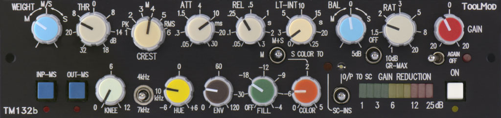
The version TM132b of the M/S Mastering Compressor comes without these additional features. Side Chain Insert
The TM132 M/S Compressor comes with a fully balanced side chain insert output and input. The side chain insert is directly assigned to the compressor input and located pre the internal side chain processing with the Weight control, the Envelope circuit, and the Hue filter. The input and output format depends on the current operation mode of the compressor and the setting of the matrix switches. If the compressor works in M/S mode, the side chain insert works also in M/S mode.
The side chain insert output is always active while a 3-position lever switch selects the side chain insert input in the 'SC-INS' position. In this case the compressor is controlled only by the signal that feeds the side chain insert input. The position O/P TO SC makes it possible to check the setting of the side chain input directly by switching the side chain signal directly to the output of the compressor. This takes place without a change of the format and independent of the operation mode and the matrix setting. The side chain signal feeds the output always in the selected format of the output. Stereo Mode
Although the TM132 Compressor is optimized for M/S operation, standard stereo
operation is possible as well. With L/R format input and output signals, stereo
mode is selected if the OUT-MS and IN-MS switches are pressed at a time. With
M/S format input and output signals, stereo mode is active when both switches
are not pressed.
While most of the controls are not affected by the selected operation mode, some controls operate differently. With stereo mode: • the WEIGHT pot regulates between left and right channel instead of M and S. Setting the pot to M controls the compressor from the left channel only and vice versa. • the BAL pot now decouples the left and right channel instead of M and S. • the COLOR TO switch routes the harmonics to the left channel in the M position and to the right channel in the S position • with the TM132 standard, that comes with the Enhance and the Elliptic switches, it is important to set these switches are to the OFF position to avoid strange behavior with stereo mode. Gain Reduction Display
A LED display with 10 LED's shows the actual gain reduction with a range of 25
dB.
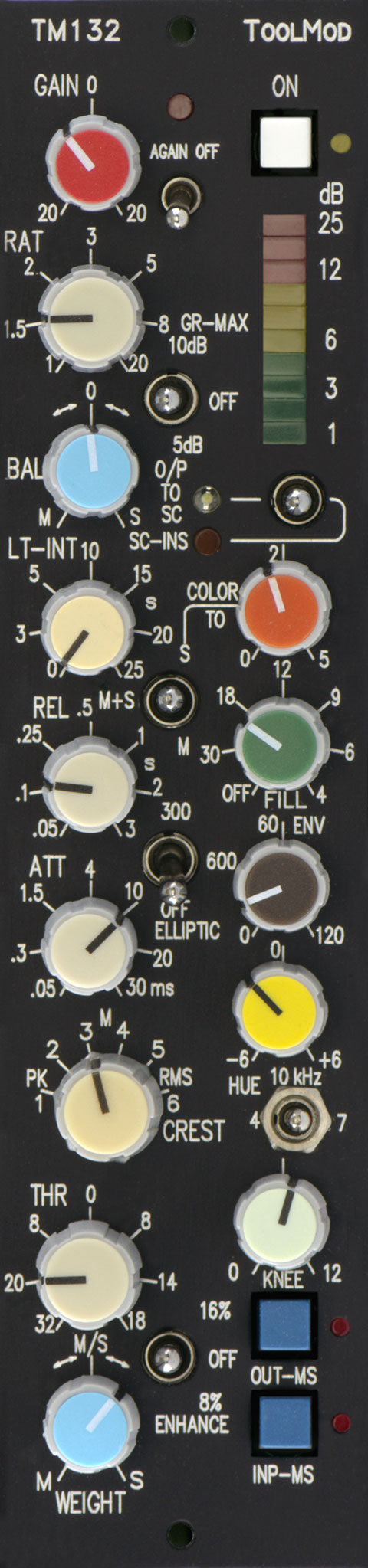
The TM132 M/S Stereo Mastering Compressor is a 4U ToolMod device. It fits into two adjacent slots of a 1U high frame and any slot of a 4U high frame. As usual, horizontal and vertical versions are available. |
|
| Newsletter |
| Where to buy | |||
| Support | |||
| Download | |||
| Tell A Friend | |||
Imprint
|
Like the TM222 Stereo Mastering Compressor, the TM132 M/S Compressor is the result of our more than 25-year experience in the design of master compressors for our large format consoles. During more than two decades, the circuits have been improved and optimized. Many users were involved in this process. Moreover, special functions that have been developed for the mastering dynamics U796 of the V700 mastering gear complete the feature set of this unique M/S Stereo Mastering compressor.
transformer Mic Pre TM102
discrete Mic Pre TM103
active DI Amp TM105
5-Band Equalizer TM107
3-Band Equalizer TM112
Compressor TM112b
VCA Compressor TM115
Brickwall Limiter TM115b
Peak Limiter TM116
Noise Gate TM130
M/S Direction Mixer TM131
L/R-M/S Matrix TM132
M/S Compressor TM133
M/S Mastering EQ TM134
4-Band M/S EQ TM204
4-Band Mastering EQ TM205
5-Band Stereo EQ TM212
Stereo Compressor TM212b
Stereo VCA Compressor TM215
Stereo Limiter TM215b
Mastering Limiter TM222
Mastering Compressor
ToolMod Sitemap